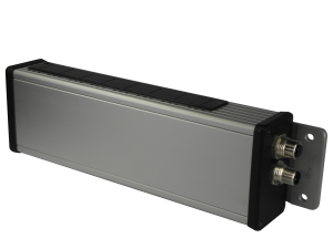
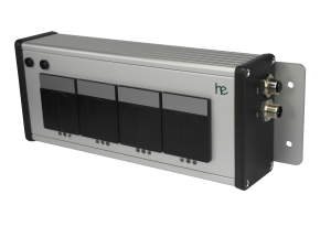
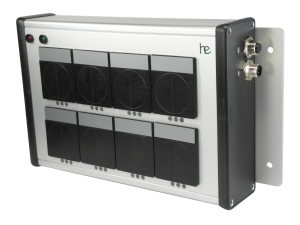
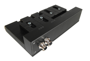
Feature Overview
Communication with the socket trays takes place via an M12 circular connector, while the MODBUS lines are forwarded via another M12 connector. The interface is used to select the desired operating mode, tool selection, feedback from the socket trays and execution of the diagnostic functionality. The control is dual-coded or bit-coded.
Further functions
Group functions and tool recognition can be parameterized using the programming cable and the software supplied.
You can find detailed information here: Programming cable
Available versions
Socket Trays |
|
type | Description |
Main module | 24V EA Parallel interface |
Main module | 24V EA parallel interface, Open Protocol variant |
Main module | Profinet slave fieldbus interface |
Main module | Profibus slave fieldbus interface |
Main module | Ethernet/IP slave fieldbus interface |
Main module | EtherCAT fieldbus interface |
extension module | Modbus slave fieldbus interface |